Creo 11
Latest Enhancements!
Creo continually introduces enhancements to make design engineers more productive, and we’re inspired by our customers’ feedback. PTC Creo 11 presents the latest version of the award-winning CAD system that is both powerful and easy-to-use. With Creo 10, you can deliver your best designs in less time. It comes with new cutting-edge composite tools, revolutionary features for electricity and ergonomics design, simulation-based designs, and impeccable Model-Based Definition (MBD) for flawless manufacturing.
PTC Creo 11 – New Features and Functionality
Explore the features of PTC Creo 11
A comprehensive CAD system for faster and smarter product development.
Exceptional usability and productivity
With every release, Creo introduces improvements to make design engineers more productive every day.
Creo now supports multibody concepts for designs containing multiple sheet metal and regular bodies, allowing you to better design sheet metal parts in context.
In addition, you can now transfer solid bodies from parts of an assembly into a single multibody part using the Shrink-wrap feature, making it easier and faster to work with your complex designs.
Creo now features an enhanced enclosure volume feature, to optimize and calculate the minimum bounding box of your part or assembly for packaging optimization.
Creo 11 Composites
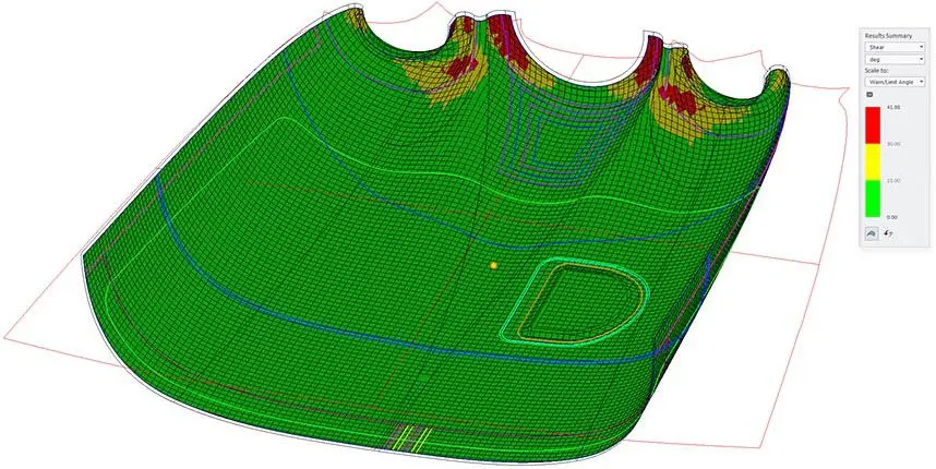
Design engineers are finding applications of composite materials in more products than ever, and Creo 11 continues to expand composites design, simulation, and manufacturing capabilities. Creo has expanded functionality for transitions, laminate sections, and draping simulations. You can even use zone-based design to define and automatically build plies from zones. Manufacturing has been enhanced with extended ply boundaries, core sampling and the ability to export to leading laser projection systems.
Creo 11 Electrification
Creo has improved cabling and ECAD-MCAD collaboration capabilities to power your circuitry and cabling designs.
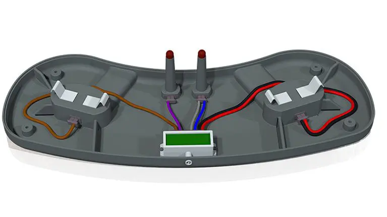
Cabling tools for manipulation of locations have been improved. Locations can now be placed tangent to any Coordinate System axis and the “Remove Locations” tool has been completely overhauled for easier use. Placement of custom components and splices has been enhanced, and harness settings can now be changed during routing. Additionally, the cabling tree has been updated for greater visibility of harness structure and cabling entities.
ECAD capabilities have also been extended with the addition of Transparency Control, for improved visibility of PCB stack-up and overlapping ECAD layers.
Model-based definition
Creo now gives you even more powerful model-based definition tools to provide greater clarity with less effort. Now you can easily organize your design data in simple tables that can be read by humans and machines, with both user-defined text, parameter callouts, and semantic references.
Creating MBD annotations for cylindrical features is quicker, and semantic query is now available for inheritance models. GD&T Advisor has been updated to support ISO 22081 standard for general tolerances, for combined simplified hole callouts and enriched definition for slab and slot features.
Simulation-driven Design
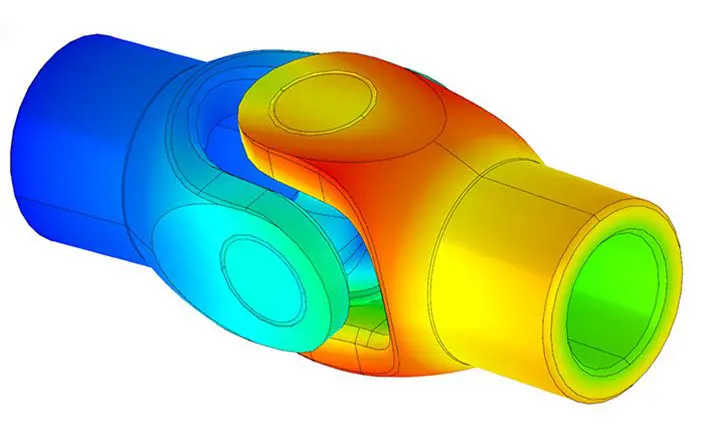
PTC Creo 10 has advanced significantly in the aspect of simulation-driven design. With features like Creo Ansys Simulation Advanced, including support for nonlinear materials, users can model complex parts and optimize designs with ease. Contact simulation options are now included in Creo Simulation Live, alongside improved fluid and structure result options. Furthermore, both Creo Flow Analysis and Creo Simulate have received enhancements to enable better animation and multibody support. That’s not all. Generative design features in Creo have been improved with additional functions such as rotational symmetry, remote loads, and mass point constraints, that you don’t want to miss.
Computer Aided Manufacturing
As always, Creo has improvements for both additive and subtractive manufacturing. For additive manufacturing, you can now connect two or more lattices with different cell types on a single continuous lattice structure and adjust pore size control for stochastic lattices. In addition, Creo has also expanded 3MF STL export options.
For subtractive manufacturing, High-Speed Milling now features 4-Axis rotary milling, plus trajectory milling enhancements. And 4-Axis area turning user interface has been improved, too.
What is the composite design and manufacturing process?
The composite design and manufacturing process typically involves the creation of ply book drawings, which detail the specific arrangement and orientation of composite plys in a component. These drawings or flat patterns are crucial for ensuring the correct stacking sequence, fiber angles, and material choices to meet design requirements. The process includes design, engineering analysis, layup, quality control, and manufacturing, all guided by the information provided in the ply book drawings to achieve the desired composite part.

Links to Other Pages
- Creo Parametric: Discover the powerful capabilities of Creo Parametric for parametric 3D CAD design.
- Creo vs Solidworks – Comparison Chart: Compare Creo and Solidworks side by side with our detailed comparison chart.
- Creo Simulation Live: Explore how Creo Simulation Live can help you perform real-time simulation directly within your CAD environment.
- ANSYS Simulation for Effective Engineering Analysis: Learn how ANSYS simulation tools can enhance your engineering analysis for more effective results.
Looking For Something Specific?
Need assistance with TriStar PLM Solutions? We’ve got you covered! Don’t hesitate to reach out if you can’t locate what you need. Call us at 800-800-1714 for any inquiries, or contact us to leave a quick message with your questions – we’re here to help!
Below, you’ll find additional recommended resources just for you:
Related Documents
Related Resources
Related Webinars
THE LATEST CAD NEWS AT TRISTAR
Product Sustainability for Businesses: A Practical Guide to Smarter, Long-Lasting Products
Discover how manufacturers can take practical, profitable steps toward product sustainability. This no-fluff guide breaks down complex processes, regulatory insights, and lifecycle strategies to help you drive real business value—without getting overwhelmed.
10 Creo View Tips to Take Your Visualization Skills to the Next Level
Creo View is a powerful tool for extending your digital thread beyond CAD, but many teams aren't using it to its full potential. This article shares ten practical tips—plus a bonus—for improving your visualization skills with Creo View. From clean component displays and intuitive sectioning to publishing feature dimensions and managing inseparable assemblies, these tips help streamline collaboration, enhance design reviews, and make downstream usage easier across your organization. Whether you're using Creo View Lite, Express, or MCAD, there's something here to level up your workflow.
Webinar Replay: Advanced Assembly in Creo
Missed our live webinar on Creo’s Advanced Assembly Extension (AAX)? Watch the replay to see how AAX simplifies Top-Down Design, streamlining complex assemblies with Skeletons and Master Models for better organization, flexibility, and efficiency. Learn how to optimize workflows, reduce errors, and boost productivity with Creo’s powerful assembly tools.
