March 24, 2025
10 Creo View Tips to Take Your Visualization Skills to the Next Level
READ TIME: 6.4 MINS
Overview
Increasing the usage of Creo View is a great way to extend the Digital Thread from CAD to other workstreams across your organization. Many companies already have Creo View and CAD publishing in place, which makes this initiative more about awareness, understanding downstream use cases and supporting people as they begin using this tool.
There are three levels of Creo View software.
- Creo View Express is a free download that will allow users outside of your company to utilize the PVZ files.
- Creo View Lite comes with Windchill and is a good place to start.
- Creo View MCAD requires an additional purchased license but brings additional functionality for Interference Checking, 3D geometry compare, part color changes and more.
It is important to note that many of the tips covered in this article can also be used with Creo Illustrate.
Precisely Exploding Components
There are two ways to precisely position components when translating and rotating:
- When dragging a component, you can simply type in the needed translation distance or rotation angle and press [Enter]. The trick is to begin translating, keep the left mouse button held down, and then enter the value.
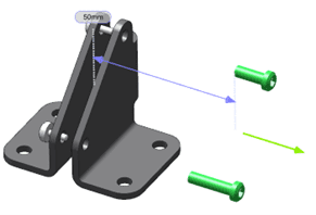
Figure 1
- Hold the [Ctrl] and [Alt] keys while dragging to display the ruler. When dragging, components will “snap” to the ruler increments. The snapping increments are set in the Options dialog. Rotation shows a “protractor” for angular increments.
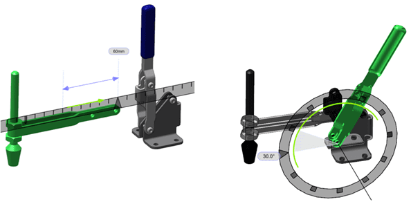
Figure 2
Improved Selection Display
By default, selecting a component will highlight it in green and also show the bounding box. The box is annoying screen clutter and can be disabled using File > Options > Global > Model and uncheck Highlight part using bounding box. This is a cleaner look for design reviews.
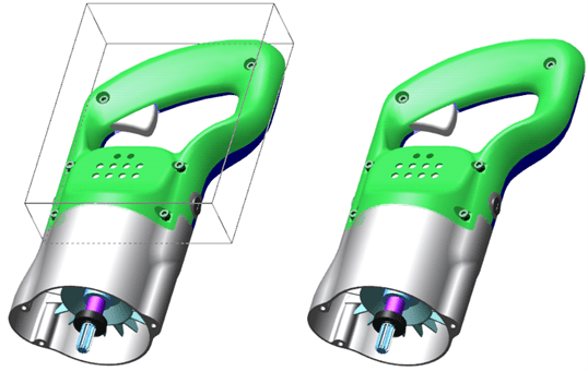
Figure 3
Quick Parent Assembly Selection
A cool selection trick is to select a component and use the left arrow key to select the component’s parent assembly on the screen and in the structure. Hitting the left arrow key again will select the next level higher parent assembly. Hitting the right arrow key moves down in the structure. This technique is very useful to quickly select subsystems when translating components, hiding components and isolating components.
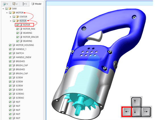
Figure 4
3D/2D Sectioning
Sectioning in Creo View has advanced capabilities typically found in 3D CAD software. Setting the section cap and section line colors will make visualizing the components easier in 3D. The 2D section can be opened in an additional window where measurements and visual analysis can happen. The 3D and 2D section windows are synchronized and update together when the section plane is moved.
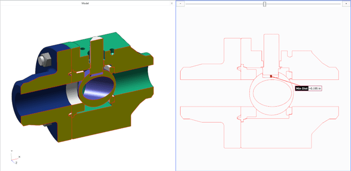
Figure 5
Please note, the Recipe File used for publishing in Windchill or from Creo Parametric can be enhanced to have Creo Parametric Cross Sections published into the Creo View viewable files.
Improving the Default Color
Components that do not have a color assigned in the native CAD tool are published using the default “primitive” color, which is black. This coloring can make seeing the geometry complicated as shadows and contours are less visible. To change this, go to Options > Active View > Color and change the Default color. This technique is useful for people using Creo View Lite, which does not have another way to change component color.
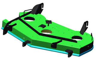
Default Primitive Color
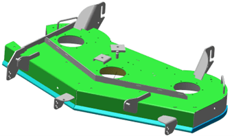
Updated Primitive Color
Improved Shaded Edge Display
Thick/Thin Edge display eliminates the internal patch lines present from the CAD modeling approach and highlights external edges in black. It adds definition to the components while cleaning up the display and really makes the model “pop” for people that are not using Creo Illustrate. First, set the Render Mode to Shade With Edges. Next, in File > Options > Model disable Flat Polygon Shading. Lastly, add the Thick/Thin icon to the Quick Access Toolbar and enable it.
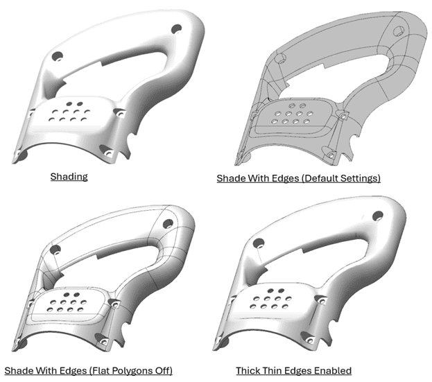
Figure 7
Try this one your models to see the improvement for design reviews and image creation.
Adding Meaningful Information to the Structure
The names of the components in the Model Structure Viewer are based on the CAD file names and may not be very meaningful. A simple improvement anyone can make is to add additional columns to the tree to display additional information from each model. Click Options > Navigation > Use tree columns to enable this.
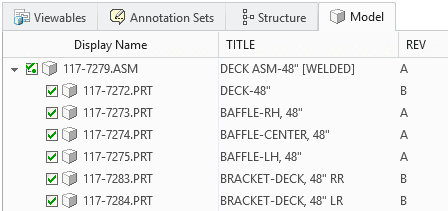
Figure 8
If the information you want to display is not available to add as a column, an alternate approach is to enhance the display name to include attributes. There appears to be more attributes available using this method. Click Options > Navigation > Use alternate part name to enable this.
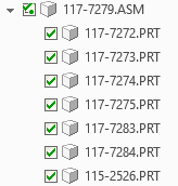
Original Names
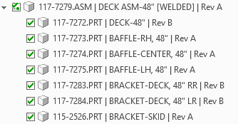
Customized Names
Publishing Feature Dimensions
The Recipe File used for publishing in Windchill or from Creo Parametric can be enhanced to have feature dimensions viewable in the Creo View models. This may increase the efficiency of measurement and inspection tasks by passing the dimensions and design intent along the Digital Thread. Please note, the dimensions will appear in the exact location where they were left during feature creation.
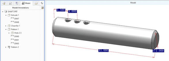
Figure 10
This is a low effort first step that will push dimensional data downstream. Proper CAD modeling standards will be critical to ensure sketches do not have “zero” dimensions, do not have weak dimensions and dimensions are located “off the model” where they can be clearly seen.
Utilizing 3D Drawings
Model Based Definition (MBD) has been a hot topic for years. Model annotations can be defined in Creo Parametric and published through to Creo View in a manner that is easy to display and hide. This approach provides a nicer output and is easier to work with than simply publishing the feature dimensions noted in the prior tip. However, it will take some additional work by the CAD modeler or Detailer to position the dimensions with the same intention as in the 2D drawing.
This functionality is very drawing-like and impressive. Combination States are used to show/hide annotations, set the view orientations, show/hide cross sections, add on-screen notes and a title block. All of this publishes through to the Creo View models very nicely.
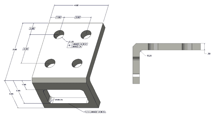
Figure 11
Interference Detection
Creo View MCAD can perform interference checks between all parts, specific parts or between sub-assemblies. Creo View offers a slick set of analysis tools that can be used to review each interference pair found by isolating the two interfering parts, consistently coloring them, showing the interfering volume and sectioning the models to reveal interior geometry.
The rest of the assembly can be shown in phantom to help understand where in the interfering components reside in a complex assembly.
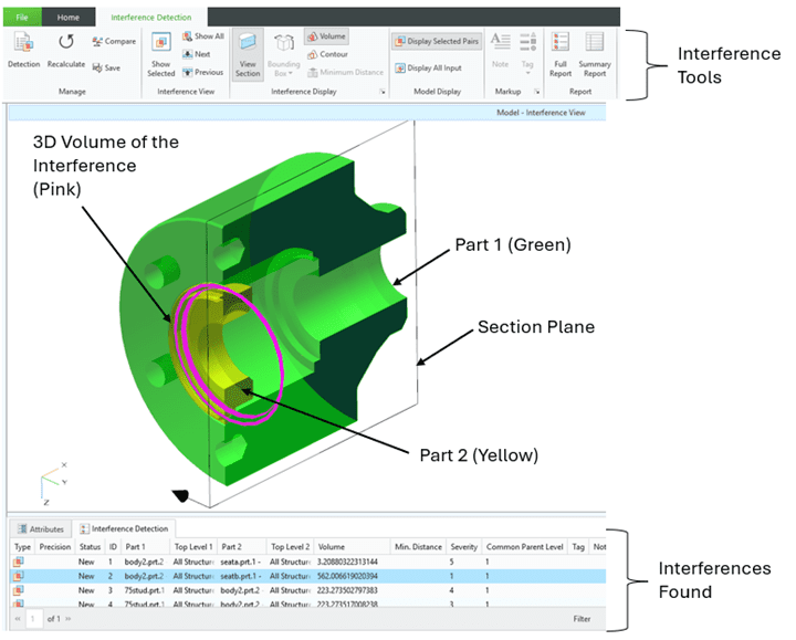
Figure 12
Bonus: A New Way to Handle Outsourced Models
Inseparable Assemblies arrived in Creo Parametric 9 and will embed the component model PRT and ASM files within the top level ASM file. It is checked into Windchill as a single ASM file without components, yet the components remain editable in Creo Parametric. This also results in one WTPart file.
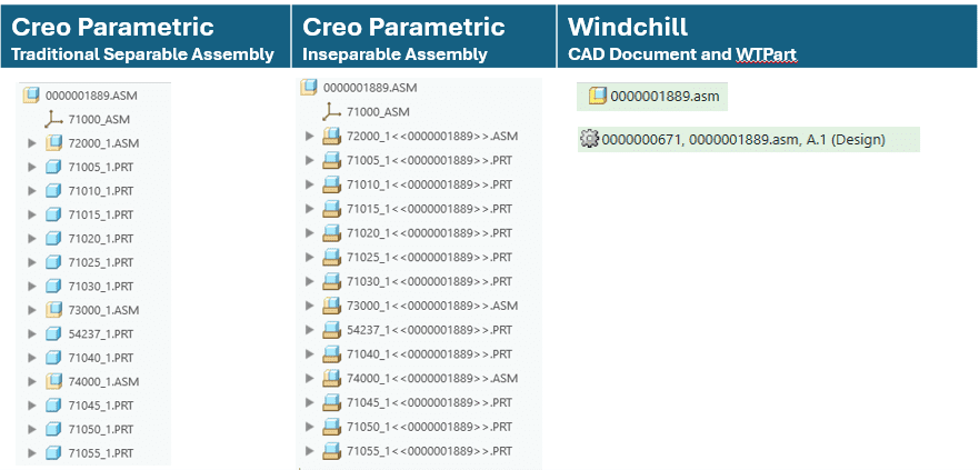
Figure 13
However, when published and opened into Creo View, the individual components can be manipulated independently (shown, hidden, colored, exploded, etc.), providing downstream users the fidelity needed for illustrations and deeper investigations.
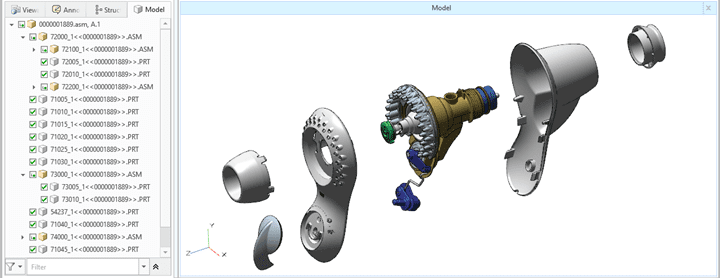
Figure 14
A perfect application for this is the 3D models for purchased assemblies, where Design and Manufacturing prefer to work with one object (the inseparable assembly and WTPart) and Service teams want to see each individual component. This will work when using native Creo Parametric assemblies or import files.
Partner with TriStar for Visualization and Publishing
There is a lot more to learn about Creo View than what is mentioned in this article. Each of the topics discussed here have more details to uncover and there are additional capabilities as well. Connect with us if you are interested in talking with a Tristar expert about Creo View or any of these areas:
- CAD Worker Setup and Configuration.
- Publishing tools and strategies.
- Training and Mentoring for Creo Parametric, Creo View, Creo Illustrate, Windchill EBOM/MBOM/SBOM and SLM.
- Platform Structures, Smart Platforms and Product Configurators.
About the Author

Andrew.Burke@Tristar.com
Andrew Burke has been working with PTC solutions for over 30 years starting as a Design Engineer designing furniture, consumer products, manufacturing equipment and medical products using the full suite of PTC design and PLM software. He later worked as a CAD Instructor, Course Developer, User Support Engineer, IS Project Manager and Technical Publications Manager. Working for companies such as PTC, Medtronic and Polaris has provided unique insights into PTC’s Digital Thread and is now the Director of Digital Transformation with Tristar.
TriStar Digital Thread Solutions welcomes questions. Feel free to CONTACT US if you can’t find what you’re looking for, or call us at 800-800-1714


Leave A Comment